Search filter
Filter
Reset- Product data sheet (888)
- Installation drawing (888)
- Installation instructions (358)
- Tender texts (296)
- 3D model (181)
- Product scale drawing (147)
- Certificate (112)
- Declarations of performance (91)
- Cable plan (76)
- Declaration of conformity (73)
- Wiring diagram (43)
- Product declaration (LEED, DGNB, EPD) (43)
- User manual (34)
- Flyer/folder (28)
- Supplementary sheet (25)
- Product brochure (22)
- Type examination certificate (11)
- T&C / Data Protection (7)
- Software (5)
- Supplier information (4)
- Customer information (3)
- Safety analysis (2)
- Evaluation/comment (2)
3339 results found

ECturn glass guide rail opposite hinge side
DOCUMENT | 649 KB
ECturn door leaf installation opposite hinge side link arm
DWG | 645 KB
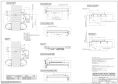
ECturn door leaf installation hinge side guide rail
PDF | 325 KB
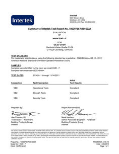
Intertek evaluation EMD-F
Intertek 8431 Murphy Drive Middleton, WI 53562 608-836-4400/ Fax: 608-836-0050 Summary of Intertek Test Report No. 100397367MID-002A EVALUATION OF Model EMD - F FOR GEZE GmbH Reinhold-Vöster-Straße 21-29 D-71229 Leonberg, Germany TEST STANDARD: Per customer's specifications, using the following standard as a guideline: ANSI/BHMA A156.10 - 2011 American National Standard for Power Operated Pedestrian Doors. SAMPLES: Samples were identified by the client as model EMD - F. Samples were tested at GEZE GmbH. TEST DATES: 5/23/2011 through 11/14/2011 Test Description Initial Test Results … Operational Tests Compliant … Strength Tests Compliant … Security Tests Compliant Subsection Prepared By: Report Reviewed By: Han Fossum, RL Technician … - Hardware Building Products Group Intertek Mark Harrison Senior Associate Engineer - Hardware Building Products Group Intertek This report is for the exclusive use of Clients of Intertek Testing Services N.A., Inc. (Intertek) and is provided pursuant to the agreement between Intertek and its Client. Intertek's responsibility and liability are limited to the terms and conditions of the agreement. Intertek assumes no liability to any party, other than to the Client in accordance with the agreement, for any loss, expense or damage occasioned by the use of this report. Only the Client is authorized to copy or distribute this report and then only in its entirety. Any use of the Intertek name or one of its marks for the sale or advertisement of the tested material, product or service must first be approved in writing by Intertek. The observations and test results in this report are relevant only to the sample tested. This report by itself does not imply that the material, product, or service is or has ever been under an Intertek certification program. Project No.: 100397367MID-002A Model No.: EMD - F Client: GEZE GmbH ANSI/BHMA A156.10 Date: 4/26/2012 Page … of 1
PDF | 56 KB
ECturn transom installation opposite hinge side guide rail
DWG | 613 KB
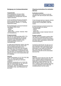
User manual Cleaning of activation devices
Reinigung von Ansteuerelementen Cleaning instructions for activation devices Taster/Schalter Die Reinigung kann mit einem milden Reinigungsmittel durchgeführt werden, anschließend mit Leitungswasser (feuchter Lappen) abwischen. Pushbuttons/switches The cleaning can be carried out with mild detergent, then wipe with plain water (damp cloth). Ist eine gründlichere Reinigung erforderlich, können Lösungsmittel, wie aromatenfreie Benzinfraktionen, Alkohole u. a., vorsichtig angewendet werden. If more thorough cleaning is required, solvents such as aromatic-free gasoline fractions, alcohols can be, among others, used with caution. Bei Raumtemperatur und kurzer Einwirkzeit sind folgende Mittel erlaubt: - Petrolether - Spiritus - Ligroin und - Alkohol (Ethyl-, n-Propyl-, Isopropyl-, Butylund Isobutylalkohol) At room temperature and short reaction time the following agents are allowed: - Petroleum ether - Ethanol - Ligroin and - Alcohol (ethyl, n-propyl, isopropyl, butyl and isobutyl alcohol) Programmschalter Die Folie der Programmschalter (MPS, TPS, DPS) ist von hinten bedruckt. Sie hat eine chemische Beständigkeit gegen Alkohole, verdünnte Laugen und Säuren, Ester, Kohlenwasserstoffe, Ketone und Haushaltsreiniger. Program switches The film used for the program switches (MPs, TPS, DPS) are printed from behind. It has a chemical resistance to alcohols, diluted alkalis and acids, esters, hydrocarbons, ketones and household detergents. Es sollte darauf hingewiesen werden, dass das feuchte Abwischen nicht dazu führen darf, dass Desinfektionsflüssigkeit an den Stirnflächen der Folie in die Folie eindringen kann. Dies würde mit Sicherheit im Laufe der Zeit zur Verfärbungen im Außenbereich hinter der Folie führen. Im schlechtesten Fall zu einer Ablösung der Folie von der Zwischenfolie oder der Leiterplatte. It should be noted that the wet wipe may not allow disinfection liquid to penetrate the end faces of the film. This would certainly lead to discoloration in the outside area behind the film. In the worst case, it would lead to a detachment of the film from the intermediate foil or the PCB. Sensorik Drehtür-Sensorleisten (z.B. GC 334, 335, 338): IP52 – d.h. Schutz gegen fallendes Tropfwasser (also hier auch nicht direkt anspritzen) Schiebetür-Kombimelder (z.B. GC 363, 363, 365) und Lichtvorhänge (GC 333, 339, 341): IP54, d.h. Schutz gegen allseitiges Spritzwasser (aber nicht gegen Spritzwasser mit erhöhtem Druck oder Strahlwasser aus der Düse!) Sensors Swing-door sensor strips (GC 334, 335, 338): IP52 – Protection against splashing water (Direct splashes should be avoided, here, too.) Sliding-door combined detectors (GC 363, 365) and light curtains (GC 333, 339, 341): IP54 - Protection against splashing water (but not against splashes or jets of water with increased pressure from the nozzle)
PDF | 66 KB
ECturn door leaf installation hinge side guide rail
DOCUMENT | 6 MB
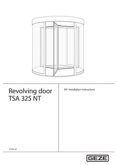
Installation instructions TSA 325 NT revolving door
Revolving door TSA 325 NT 131904-05 EN Installation instructions Revolving door TSA 325 NT Table of contents Symbols and illustrations … Product liability … 2 … Security … Intended use … Safety instructions … Safety conscious working … Inspection of the installed system … Environmentally conscious working … 2 Tools and aids … General tool set … Special tools … Consumables … 3 Structure … 4 Installation … Preparations to be made on site … Mounting the revolving door TSA 325 NT … Mounting switch contact strips on the leaves … 22 Connect the GEZE ST220 diagnostic device/Use GEZEconnects … 23 Mount the ceiling panel … 24 Check list for commissioning and service … 27 … Options … 28 … Automatic locking system … 28 Revolving doors with breakout function … 33 External night time closer (automatic and manual) … 41 Open position monitoring … 43 General installation information for NV tooth-belt tension … 44 Revolving door in all-glass version (TSA 325 NT GG) … 50 Speed limiter unit for TSA 325 NT … 61 … Revolving door TSA 325 NT RC … 64 … Assemblies and parts … 64 Revolving door TSA 325 NT RC … 65 Installing revolving door TSA 325 NT RC … 68 Installation information for NV tooth belt tension RC2 … 86 Mounting the turnstile … 87 Mounting contact strips on the leaves … 87 Mount the RC … ceiling panel … 87 Check list for commissioning and service … 94 … Revolving door TSA 325 NT, 3-leaf … 95 … Assemblies and parts … 95 Night-time closer drive (AINV) … 96 Mounting the TSA 325 NT revolving door, 3-leaf … 97 Installation information for NV tooth-belt tension … 108 Mounting the turnstile … 108 Mounting contact strips on the leaves … 109 Mount the RC … ceiling panel … 109 Check list for commissioning and service … 109 Revolving door TSA 325 NT Security Symbols and illustrations Warning notices In these instructions, warning notices are used to warn against material damage and injuries. XX Always read and observe these warning notices. XX Observe all measures marked with the warning symbol and warning word . Warning symbol Warning word Meaning WARNING Danger to persons. Non-compliance may result in death or serious injuries. CAUTION Danger to persons. Non-compliance can result in minor injuries. More symbols and illustrations Important information and technical notes are highlighted to explain correct operation. Symbol Meaning means “important information”; Information on avoiding material damage, understanding a concept or optimising the operation sequences means “additional Information” XX Symbol for an action: This means you have to do something. XX If there are several actions to be taken, keep to the given order. Product liability In compliance with the liability of the manufacturer for his products as defined in the German “Product Liability Act”, compliance with the information contained in this brochure (product information and intended use, misuse, product performance, product maintenance, obligations to provide information and instructions) must be ensured. Failure to comply releases the manufacturer from his statutory liability. … Security To ensure personal safety, it is important to follow these safety instructions. These instructions must be kept. … Intended use àà The revolving door TSA 325 NT is solely suitable for use in entrances and interior areas of pedestrian traffic in commercial plants and public areas. àà The revolving door TSA 325 NT may not be used as a fire or smoke proof door drive. àà The variants of the revolving door TSA 325 NT with break-out leaves is suitable for use in escape and rescue routes. … Security … Revolving door TSA 325 NT Safety instructions àà The mandatory installation, maintenance and repair work must be performed by properly trained personnel authorised by GEZE. àà The country-specific laws and regulations are to be observed during safety-related tests. àà GEZE is not liable for any injuries or damage whatsoever resulting from unauthorised changes to the system. àà GEZE does not accept any warranty for combinations with third-party products. àà Furthermore, only original GEZE parts may be used for repair and maintenance work. àà Connection to the mains voltage must be carried out by a qualified electrician. The mains connection and equipment ground conductor test must be performed in accordance with VDE 0100 Part 610. àà Before connecting the onsite power supply circuit, a ground connection must be completed (connect to equipotential bonding). àà Use an on-site automatic cut-out as the line-side disconnecting device with locking option, the dimensioning of which is matched to the type, cross-section, type of routing and ambient conditions of the on-site feeder. GEZE recommends separate fuse protection for the door drive. àà Protect the button program switch (TPS-KDT) against unauthorised access. àà In compliance with Machinery Directive (2006/42/EC), a risk analysis must be performed and the door system identified in accordance with CE Marking Directive 93/68/EEC before the door system is commissioned. àà Observe the latest versions of directives, standards and country-specific regulations, in particular: àà ASR A1.7 “Doors and gates” àà EN 16005: 2012 “Power operated pedestrian doorsets – Safety in use– Requirements and test methods” àà VDE 0100-600 "Installation of low-voltage systems - Part … Tests” àà Accident-prevention regulations, especially DGUV A1 “General regulations” and BGV A2 “Electrical installations and equipment” àà DIN EN 60335-2-103 "Household and similar electrical appliances; Particular requirements for drives for gates, doors and windows" àà Use lifting tools adapted to the weights of the system parts. àà Check the weight distribution in the ceiling construction before lifting. àà Observe the Load Handling Regulation (LasthandhabV). The following table lists the weights of the individual components depending on their diameter (passage height here 2500 mm, canopy height 200 mm, without air curtain). Other equipment options and canopy heights may deviate: Ø 2400 Ø 3000 Ø 3600 Floor ring 25 kg 35 kg 50 kg Fixed panel 70 kg 90 kg 105 kg Ceiling structure 70 kg 90 kg 120 kg Door leaf 70 kg 85 kg 100 kg Drive unit 80 kg 80 kg 80 kg Ceiling panel 100 kg 140 kg 200 kg This appliance can be used by children aged from … years and above and persons with reduced physical, sensory or mental capabilities or lack of experience and knowledge if they have been given supervision or instruction concerning use of the appliance in a safe way and understand the hazards involved. àà Children shall not play with the appliance. àà Cleaning and maintenance shall not be carried out by children without supervision. àà The door system must be unplugged from the mains connection during maintenance and cleaning work. àà No persons may pass through the door system during repair or maintenance work. … Safety conscious working àà àà àà àà àà Secure workplace against unauthorised entry. Watch the swivelling range of long system parts. Never carry out work with a high safety risk (e.g. installing the drive, cover or door leaf) while alone. Secure the cover/drive panels against falling. Only use the cables prescribed in the cable plan provided. Cables must be shielded in compliance with the wiring diagram. àà Secure loose, internal drive cables with cable ties. àà Before working on the electrical system: àà Disconnect the drive from the 230 V mains and check to ensure that it is not supplied with power. àà disconnect the control unit from the 24-V rechargeable battery. àà note that if an uninterruptible power supply (UPS) is used, the system will still be supplied with power despite the fact that the power supply is disconnected. àà Always use insulated wire-end ferrules for wire cores. … Revolving door TSA 325 NT àà àà àà àà àà àà àà Tools and aids Attach safety stickers to glass door leaves (Mat. no. 136518). Danger of injury with opened drive. Hair, clothing, cables, etc. can be drawn in by rotating parts. Danger of injury caused by unsecured crushing, impact, drawing-in or shearing spots! Danger of injury due to broken glass! Danger of injury due to sharp edges in the drive! Danger of injury during installation through freely moving parts! Use ladders or suitable protective equipment when working at height! Working on the air curtain àà Use suitable lifting tools when installing the air curtain. àà The air curtain must be connected by a specialist company. àà When working on the air curtain, watch out for sharp edges and elevated temperatures. Observe and comply with the manufacturer's specifications. … Inspection of the installed system Measures for protection and prevention of pinching, impact, shearing or drawing-in spots: XX Complete the check points according to the check list in the document “Commissioning and service”. XX Check the function of safety sensors and movement detectors. XX Check protective earth connection to all metal parts that can be touched. … Environmentally conscious working àà àà àà àà When disposing of the door system, separate the different materials and have them recycled. Do not dispose of batteries and rechargeable batteries with household waste. Comply with the statutory regulations when disposing of the door system and the batteries/storage cells. Dispose of silicone residue according to local official regulations. … Tools and aids … General tool set àà àà àà àà àà àà àà àà àà àà … Tape measure Marking pen Torque spanner Allen key in common sizes - including … mm Open-ended wrench in common sizes Screwdriver set Personal protective equipment (PPE) Safety shoes min. class … Helmet Ladder or protective scaffolding àà àà àà àà àà àà àà àà àà Torx wrench T x 20 Side-cutting pliers Crimping pliers for cables Electric drill Mitre saw Level Protective glasses Cut protection work gloves level … Suitable work clothing Special tools Tool Size/remark GEZEconnects Diagnostic device GEZE ST220 Ring force gauge Hammer drill Welding equipment Cordless screwdriver Threader for M4–M8 and corresponding drills Specialised tool: combination spanner, angled, size 13 mm ID no. 86838 Glass suction device for curved glass surfaces Tension belts … piece with sufficient length (4–5 m) … Tools and aids Revolving door TSA 325 NT Tool Size/remark Tested lifting tools e.g. Genie Hoist … or GH … (min. lifting capacity 160 kg; max. lifting height … m or … m) Levelling device Ladder Ceiling lift Hoist unit Pneumatic punch Carrying strap Small scaffolding unit Barrier tape Cable reel with GFCI … Consumables Designation Detailed description/Remark Silicone / silicone spray àà Permitted for glass installation (laminated safety glass) àà Check local specifications to determine whether silicone / silicone spray is permitted Soap water Lithium soap universal lubricant on a mineral oil basis for the bearings Suitable underlay material/evening-out material for floor ring … e.g. Würth multi-purpose grease I Revolving door TSA 325 NT … Structure Structure … 2 … 4 … 6 … 8 … 10 11 12 Motor Top bearing Control unit Ceiling canopy Lower ceiling panels Openings for LED lights (optional) Opening for automatic locking system (optional) Automatic locking system (optional) Covers (only for manual doors) Foamed plastic disk Upper turnstile with shaft Insert sleeve centre rod 13 14 15 16 17 18 19 20 21 22 23 Side-hung casement Locking bolts Bolt lock Handle Side panels Blocks for side element profiles (optional) Floor ring Lower turnstile Floor bearing Bearing ring/bearing housing below Bearing plate/spacer … Installation Revolving door TSA 325 NT … Installation … Preparations to be made on site Check the preparations made on site by the customer to ensure proper installation: àà Type and load capacity of the façade construction or suspending frame. àà Evenness of the installation surface. àà Cable plan requirements. àà Observe installation height/metre level mark at the construction site. … Mounting the revolving door TSA 325 NT XX XX XX XX … .1 Mounting the floor ring XX XX XX … Secure workplace against unauthorised entry. Always work with a second person. Use a stepladder or step stool. Keep inside area of track clean. Lay … floor ring halves (1) and (2) together. Determine the position of the floor ring. Screw the … floor ring halves together using screws, nuts and washers. Revolving door TSA 325 NT … .2 Installation Aligning the floor ring àà In order to ensure trouble-free functioning of the revolving door TSA 325 NT, the floor ring must be aligned perfectly level (±1 mm). Top edge of finished floor level = Top edge of floor ring XX Align the floor ring every 30–40 cm using a levelling device and underlay it. XX Align the drive box as well for underfloor installation, see section … Revolving door in all-glass version (TSA 325 NT GG) on page 50. XX Aligning the centre of the floor ring: The centre of the floor ring has to have the same height as the outer floor ring (height of centre = height of outer edge) Mounting the revolving door TSA 325 NT without the floor ring is also possible optionally if the finished floor level has a sufficient load-bearing capacity. àà The installed floor ring must be protected against loading until the screed is poured. àà The visible stainless steel surface must be protected with tape! … Installation … .3 Revolving door TSA 325 NT Fastening the floor ring to the subsurface XX XX XX XX Align the bracket (1) to the floor ring and screw it to the subsurface. Align the height of the floor ring once more at these points. Weld the bracket (1) to the base of the floor ring. Option: Mount the protective plates at BO systems. … .4 Fill the floor ring space with screed. àà Take the screed height in the floor ring into account. The dimension of 22 mm in the drawing below refers to the standard entrance mats of GEZE. àà GEZE recommends sealing the surface of the screed in indoor areas. XX Fill the floor ring space (1) with screed. * Refers to the standard GEZE entrance mats Before continuing system installation, the floor ring must be checked to ensure proper dimensions. 10 Revolving door TSA 325 NT … .5 Installation Installation without floor ring The self-supporting drum structure of revolving door TSA 325 NT can be mounted directly on the top edge of the finished floor in certain circumstances. Installation without a floor ring is only permitted if the finished floor level is sufficiently load-bearing and even. Not possible for the all-glass, breakout and RC2 versions. The placement of the mounting holes for the side elements is determined in three steps: àà Determine the centre of the door system. àà Mark the interior radius (3) of the side elements on the finished floor level. àà Determine the mounting points for the side elements. àà 3-leaf doors 60° àà 4-leaf doors 45° … 2 … 4 … System axis Passage axis Interior radius Drilling radius for side panel attachment points Exterior side panel radius Determine the centre of the door system XX Precisely determine the centre of the door system and mark. Mark the interior radius XX Mark the drilling radius for the side panel mounting points (4) from the centre of the door system. Determine the mounting points for the side panels for 3-leaf door systems XX Determine the mounting points for the side panels based on the system axis (1) and the passage axis (2) according to the sketch. … 2 … 4 … 6 … 8 System axis Passage axis Interior radius Drilling radius for side panel attachment points Exterior side panel radius Line length = drilling radius (4) Line length/2 Arc size = … x floor ring/3 11 Installation Revolving door TSA 325 NT Determine the mounting points for the side panels for 4-leaf door systems XX Determine the mounting points for the side panels based on the system axis (1) and the passage axis (2) according to the sketch. … 2 … 4 … System axis Passage axis Interior radius Drilling radius for side panel attachment points Arc size = … x floor ring/4 Attach floor blocks or M6 hex screws with 10 mm head width to the floor XX Screw floor blocks (11) into the floor with countersunk screws (10). Alternatively: XX Screw M6 hex screw with 10 mm head width into the floor. Attach floor bearing housing XX Attach floor bearing housing to the finished floor, e.g. with M8 knock-in anchors (ID 121724) (2) and associated screws, e.g. M8 × 34/40 mm (1). 12 Revolving door TSA 325 NT … .6 Installation Mounting the ceiling ring XX When mounting the ceiling canopy use supports (2). XX Connect the … half-shells (1) of the ceiling canopy. XX XX Screw the … half-shells (1) (see arrows). Check the radius of the ceiling construction. Mount … spacers (approx. 4–5 mm) if necessary between the halves of the ceiling on the canopy. For larger systems: XX Place the … bars (3) with cross bars into the mounted half-shells. 13 Installation … .7 Revolving door TSA 325 NT Mounting the drive unit The drive unit (1) can be supplied premounted or separately. XX Mount the drive unit (1) parallel to the system axis (4). … 3 Outside Inside The system axis often also corresponds to the façade axis. XX Screw the drive unit (1) to the bars using … screws (4). 14 Revolving door TSA 325 NT … .8 Installation Lifting the ceiling canopy WARNING! The ceiling canopy is very heavy (approx. 200 kg). Risk of injury due to falling ceiling canopy. XX Only lift the ceiling canopy by means of suitable aids (e.g. pneumatic press). XX Do not stand under the raised ceiling ring. XX Check the weight and weight distribution in the ceiling construction before lifting! XX Use lifting tools adapted to the weight of the ceiling construction. XX Use lifting tools (2) in the passage area and raise the ceiling canopy (1) at least … cm over the side panel height. … .9 Inserting the side panel When subsequently glazing the side panels, the rules for using glazing blocks (see Gluske “Klotzfibel” glass installation guide) must be observed. XX XX XX XX Insert and align the side elements (1) into the blocks in the floor ring. Bond the glass packer into the H profile. Insert the H profile (2) between the side elements. Attach adhesive seals under the external side panels and also under the profiles to seal against non-pressurised water (see arrow). 15 Installation Revolving door TSA 325 NT XX Secure the inserted side elements against falling over by using a strap in the upper third. XX Spray soap water or silicone spray onto the upper rubber of the side elements and ceiling canopy. Lower the ceiling canopy carefully onto the side element profiles. Insert … glazing packers (min. … mm). XX XX The ceiling canopy has to lie evenly on all the side element profiles. XX If the glass has high tolerances, black silicone or wet glue may be used as an alternative to the rubber seal. … .10 Mounting the turnstile XX Insert the turnstile (2) into the chain wheel (1) and fasten it. 16 Revolving door TSA 325 NT XX Tighten the screws (3) of the clamping ring on the chain wheel crosswise to … Nm. Installation … .11 Inserting the floor bearing XX XX Screw the bearing ring (2) to the bearing plate (3) using the … screws (1). Grease the bearing housings of the bearing ring (2) well. XX Grease the floor bearing (4) well and insert it into the bearing ring (2). 17 Installation Revolving door TSA 325 NT … .12 Mounting the collector ring XX Screw the collector ring (1) to the bearing shaft (2) of the turnstile. XX XX XX Screw the circuit board DCU602 (4) to the chain wheel using the … screws (3). Connect the … cables (5) of the collector ring to the circuit board. Check chain length. View from below: The DCU602 circuit board (4) can also be delivered separately. … .13 Mounting the centre rod retainer XX XX Slide the centre rod retainer onto the top turnstile. Thread … cables (4) each for the mobile safeguarding device through the turnstile (2) and the centre rod retainer (1). The cable routing is only placed above in the bearing arms with the “mobile safeguarding device” option. 18 Revolving door TSA 325 NT Installation … .14 Drilling a cable guide for post safety XX Drill a hole for the post safety sensor cable routing at each post (2) through the ceiling canopy (1). XX Thread the post safety sensor (3) cable through the ceiling canopy. … .15 Mounting the centre rod below XX XX Guide the cable (3) through the centre rod (1) and thread it into the lower turnstile (4). Place the centre rod (1) onto the lower turnstile (4) with bearing ring (2). … .16 Inserting and aligning the drive chain 19 Installation Revolving door TSA 325 NT The chain lock must be inserted from above. XX XX Insert the drive chain (1). Check whether the drive pinion (3) and the chain wheel (2) are flush. … .17 Mounting the side-hung casements XX Insert the side-hung casement (1). Side-hung casements must be blocked on the construction site according to the blocking rules when installing glass (see Gluske “Klotzfibel” glass installation guide). 20 Revolving door TSA 325 NT Installation … .18 Fastening the side-hung casements XX XX Screw the side-hung casements at the top and bottom with … screws each (2) onto the turnstile. Insert the … cover caps (3) (accessories). The centre rod (1) can be turned to cover existing drill holes. XX Mount the other side-hung casements (3-leaf / 4-leaf) in the same manner. Above 3000 mm system diameter, turnstile braces (3) can be mounted between the side-hung casements as an option. 21 Installation Revolving door TSA 325 NT … .19 Adjusting the chain tensioner XX XX XX XX Loosen the … screws (1) at the chain tensioner (4). Tighten the drive chain (2). The indicator (3) must be positioned in the green area. Place the chain tensioner between the chain wheels and vertically to the chain. Tighten the … screws (1) again. … Mounting switch contact strips on the leaves XX Pull at least one side of the switch contact strip (2) out of the profile (1). XX Screw the switch contact strips (2) to the leaf (3) using … M4 screws (4) each. XX Attach the switch strip to the profile using the prepared drill holes. The strip must be attached using M4 threads and associated screws or comparable self-tapping screws. 22 Revolving door TSA 325 NT XX Installation Press the locking lips on the switch contact strips (2) back into the profile (1) using a lubricant (such as soapy water). XX XX XX … .1 Lay the cable from the heel protection strip through the provided drill hole into the leaf profile and into the centre rod. Wire the heel protection strip. In the same way mount and wire the heel protection strips to the other side-hung casements. Mounting the position sensor Mount and align the position sensor (1). Max. distance of position sensor to magnet = 15–20 mm Final fixing is carried out after commissioning. XX … .2 Wiring the revolving door WARNING! Risk of fatal injury due to electric shock! XX The electrical system (230 V) may only be connected and disconnected by a professional electrician. XX … Wire the revolving door TSA 325 NT in accordance with the wiring diagram. Connect the GEZE ST220 diagnostic device/Use GEZEconnects XX Connect the diagnostic device GEZE ST220 (mat. no. 137343) to the interface module (1). If the interface module (1) is not available, the ST 220 can also be inserted onto the back of the keypad programme switch. XX Start up the system with control element GEZE ST220 (serial no. 087261) or GEZEconnects (serial no. 133367). Information on commissioning the system is available in the DCU6 wiring diagram. 23 Installation Revolving door TSA 325 NT … Mount the ceiling panel … .1 Placing the cover XX Lay the cover (1) (wooden panel or aluminium sheet) on the ceiling ring. XX Screw the cover on tight (1). Bond the sheeting (4). Mount the weather guard with water gutter (5). Place weight over the entire surface of the sheeting until the glue is dry. XX XX XX … 2 … 4 … XX 24 Ceiling canopy Insulation Cover Sheeting Water gutter Seal the water gutter on the construction site (see arrow). Revolving door TSA 325 NT … .2 Installation Inserting and screwing on the segment sheeting For doors with a turnstile brace, the ceiling panel with hole must first be inserted into the ceiling. XX XX Drill the holes for the locking bolts of the manual and automatic locking system (optional). Place and align segment panels (1) on the centre ceiling panel (2) and align. XX XX In the area of the retainer profile (4) of the ceiling panels, drill the segment panels (1) and cut an M4 thread into the retainer profile. Screw in the segment panels with M4×10 countersunk head screws (3) (2 screws per panel). 25 Installation … .3 Revolving door TSA 325 NT Installing the entrance mat XX Install the entrance mat (1) according to the installation plan (see below). Installation plan X division Installation plan Y division 26 Revolving door TSA 325 NT … .4 Installation Façade connection (optional) The façade connection is an equipment option, and can be included in the scope of delivery if requested by the customer. The façade connection consists of the following components: àà 10 mm flat material; to compensate between the drum wall and canopy àà U profile; to mount the façade panel àà Façade panel; thickness, width and colour as requested by the customer àà Cylinder head screws (M4×20); included in the screw box/assorted box … 2 … 4 … 6 XX Place the flat material (5) on the butt connector strip (6) of the side panel with a thin silicone joint (7). XX Place the U profile (4) on the flat material (5) with a thin silicone joint (8). Screw the flat material (5) to the butt connector strip (6) using M4x20 cylinder head screws (3). Insert the side façade panel (2) into the U profile (4) and connect to the existing façade. Attach the top façade panel profile (1) above the door to the façade using appropriate steps and seal. XX XX XX … Façade profile, top Façade panel profile, side, left, and right Cylinder head screw M4×20 U profile, left and right Flat material, left and right Butt connector strip, left and right Check list for commissioning and service XX Complete the check points according to the check list in “Commissioning and service”. 27 Options Revolving door TSA 325 NT … Options … Automatic locking system … .1 Components … 2 … 4 … 6 … .2 Limit switch for locking bolt Retaining plate Locking bolts Drive Operating cam … Operating cam … Hexagon size … of manual unlocking Mounting the locking ramps at the TSA 325 NT XX Mount the locking ramp (1) on the moving leaf at the pre-drilled position (approx. 95 mm from the outer leaf edge (2)). The leaf will then be inside when in night position. … .3 Mounting the locking ramps at the TSA 325 NT BO XX 28 Mount the locking ramps at the two moving leaves that are positioned inside in the night position at the pre drilled positions (approx. 95 mm from the leaf outer edge (2)). Revolving door TSA 325 NT … .4 Options Installation positions Installation position TSA 325 NT, 3-leaf: Outside … 2 Side-hung casement Locking Inside Installation position TSA 325 NT, 3-leaf, Variant BO: Outside … 2 Side-hung casement Locking Inside 29 Options Revolving door TSA 325 NT Installation position TSA 325 NT, 4-leaf: Outside … 2 Side-hung casement Locking Inside Installation position TSA 325 NT BO, 4-leaf: Outside … 2 30 Side-hung casement Locking Inside Revolving door TSA 325 NT Setting the position of the locking systems The locking system has to be set so that it is as close as possible to the ceiling panel without touching it. … .5 Options … 2 … Ceiling panel Locking ramp Locking WARNING! Risk of fatal injury due to electric shock! XX Before working on the electrical system, disconnect the system from the 230 V mains network. XX XX Dismantle the ceiling panels (1) in the area of the locking systems. Adjust both locking systems by means of the oblong holes of the retaining plates. 31 Options Revolving door TSA 325 NT XX XX XX XX XX … .6 Adjust the turnstile so that the leaves are not positioned under the locking systems. Use the manual unlocking (hexagon size 6) (see section … .1 Components on page 28, Item 7) to position both locking systems completely at the bottom. Turn the turnstile until at least one of the two locking systems latches in. If necessary, adjust the locking system that does not yet latch in correctly by means of the oblong holes as described above so that it also latches in correctly. Use the manual unlocking to position the locking systems at the top again and repeat the process until both locking systems latch in when the turnstile is turned. Adjusting the switching points Adjusting of the switching points is used to specify the respective end points (locked/unlocked) of the locking bolt. If the switching points are set incorrectly, the switching contacts are not operated at the end points of the locking system so that malfunctions can occur. XX Loosen the setscrews (3) of the two operating cams (4) and (5) on the extended motor axis of the locking unit. Adjusting the locked position: XX XX XX Use the hexagon of the manual unlocking (6) to move the locking bolts completely downwards. Turn operating cam … (4) in the direction of rotation of the motor axis (see arrow) on the limit switch (2) until it triggers the contact (click noise). Tighten the setscrew (3) of operating cam … (4) again. Adjusting the unlocked position: XX XX XX Use the hexagon of the manual unlocking (6) to move the locking bolts completely upwards. Turn operating cam … (5) in the direction of rotation of the motor axis (see arrow) on the limit switch (1) until it triggers the contact (click noise). Tighten the setscrew (3) of operating cam … (5) again. 32 Revolving door TSA 325 NT … Revolving doors with breakout function … .1 Installing the central spin axis XX Remove the protective panel (1). Pre-mount the floor bearing (2). XX Place the lower disk (2) on the floor bearing. XX Options XX Unscrew the … screws (4) from the upper breakout mechanism (3). 33 Options Revolving door TSA 325 NT XX Lift the bearing plate of the upper break out mechanism (3). XX Insert the steel tube (5) of the swivelling axis onto the lower disk (2) and into the upper break-out mechanism. Ensure that the disk and the upper break-out mechanism are exactly flush. 34 Revolving door TSA 325 NT XX XX Options Secure the steel tube against twisting and slipping at the top and bottom with … fitting keys (6) each. Secure the fitting keys with M3 screws. Secure M3 screws with thread lock. Removing fitting keys: XX Screw the M3 screws out of the fitting screws. XX Screw in M4 screws and press out the fitting screws with a pull-off tool. Fitting screws can be removed by using a screw with a larger thread and a pull-off tool. XX … .2 Fasten the suspension plate of the upper swivelling axis so that the central swivelling axis is position exactly vertically. Install BO leaf The BO leaves are pre-mounted and cabled completely in the factory (including the lower BO axis and the upper BO flange). lower BO axis (7) upper BO axis (8) 35 Options Revolving door TSA 325 NT XX Turn the central spin axis (9) so that the hole of the BO axis of the leaf (7) that is to be mounted points sidewards to the middle of the side elements (11), i.e. in the direction of the swivel axis (10) shown below. The ceiling mounting ring (14) has to be adjusted upwards so that the upper BO flange can be screwed on. Loosen the lock nuts (12) of the … screws (13). Turn in the … screws. The ceiling mounting ring (14) is pressed upwards. XX XX 36 Revolving door TSA 325 NT XX Options Insert the lower BO axis into the disk (2). XX Swivel in the upper BO flange (8) and screw tight with four screws (15). 37 Options Revolving door TSA 325 NT Remove the stress from the locking pin by turning the adjustment screw (16) counterclockwise. The adjustment screw (16) has to contact lightly. The leaf latches into the BO lock. XX Turn the adjustment screw (16) ¼ of a rotation clockwise. The opening assistance is pre tensioned. XX The corresponding leaf (17) is always located to the right of the adjustment screw (16). XX Loosen the fastening bolts (19) of the bosh angle (18). XX Adjust the bosh angle using the threaded rod (20). When the leaf latches in, the locking pin has to latch into the contour of the bosh angle without a perceptible play. 38 XX Tighten the fastening bolts (19). XX Check whether the threaded rod (20) contacts at the corner bracket (21). Revolving door TSA 325 NT … .3 Options Checking the switching disk XX XX Mount the switching disk (2) on the upper BO flange so that the roller (3) of the switch is located in the recess of the switching disk in the leaf zero setting. Screw in the screws (1) with thread lock. If the roller (3) does not fit exactly into the recess, the switching disk (2) can also be turned. … .4 Connecting the lines XX Connect the wires (1) of the BO leaf to the terminal (2) on the turnstile cover. … .5 Adjusting the break-out forces of the BO leaves XX For break-out doors, increase the break-out force on one or two leaves (depending on the number of leaves) so as to prevent the leaves from becoming wedged against one another. Locking the central spin axis into position In order to adjust the break-out forces of the leaves the system has to be locked in position via the central spin axis. Insert a tool (e.g. screw driver) through the hole in the bearing disk (1) and counterhole in the floor bearing disk (2) in the floor bearing. The central spin axis is locked in position. XX 39 Options Revolving door TSA 325 NT Measuring the break-out force Measuring devices: àà Force measuring tool àà Spring scale Mark the measuring point (4) in accordance with the adjacent drawing. XX Measure the break-out force of the individual BO leaf at the measuring point (4). The maximum break-out force amounts to 220 N. XX Adjusting the break-out force XX If necessary, adjust the break-out force at the adjustment screw (5). Checking the EMERGENCY STOP function: XX Checking the EMERGENCY-STOP push button. XX Load the BO leaf. The BO leaf may not break out. Check the break-out angle XX Check whether the drive is switched off after a leaf break-out angle of 15°. … 4 … Central swivelling axis Measuring point Adjustment screw … .6 Additional information for commissioning XX XX XX XX 40 Adjust the maximum speed in accordance with the wiring diagram. Adjust the maximum acceleration so that the break-out door leaf does not break out at an EMERGENCY-STOP during the acceleration phase. If necessary, increase the “distance of acceleration”. If possible, connect revolving doors with break-out system to the façade on the canopy. Attach a “Breakout” sticker to the leaf at a height of 1000 mm above the floor. Revolving door TSA 325 NT … Options External night time closer (automatic and manual) WARNING! Danger of injury due to broken glass! XX Always mount the door leaf together with another person. XX XX XX XX Hang the door leaf (2). Use the adjusting screw (1) to adjust the door leaf to the correct height. Align the height on the basis of the brush height. Check whether the door leaf moves smoothly. XX XX XX Adjust the space between the night-time closer and the side element. Align both door leaves in the closed position at the top and bottom so that the space s at the top and bottom is the same. Screw the leaf tight and close the doors correctly. The floor guide for the night-time closer depends on the size. Observe the drawing! … .1 Mounting the automatic night locking system XX Install the toothed belt in the carrier (1) and screw it tight. 41 Options Revolving door TSA 325 NT XX Mount the emergency stop switch (option) (2). … .2 Mounting the manual night-time closer XX XX Mount the rosettes (2) for the lock. Mount the emergency stop switch (option) (1). … .3 Mount the emergency stop switch tappet contact XX Adjust the pusher contact of the emergency-off switch so that the contact switch has a distance of … mm. The spring-mounted magnet (1) will only be included in the scope of delivery for manual night-time closers. The bracket holder (2) for the tappet contact must be attached to the exterior canopy panel (3). 42 Revolving door TSA 325 NT … Options Open position monitoring àà The leaf part of the tappet contact must be mounted on the roller carriage before installing the leaf. Subsequent installation on the roller carriage is not possible. àà The leaf part tappet contacts can only be mounted on an RC … roller carriage. Mounting the tappet contact on a track The tappet contact consists of a leaf part and a frame part installed in the track. XX XX XX Before installing the night-time closer, mount the leaf part (1) on the associated RC … roller carriage. After installing the leaf in the track, align the door leaf and check for proper running behaviour, including in conjunction with the tooth belt (optional: automatic night-time closer). After aligning the leaf, push the frame element tappet contact (2) into the track from below and position in the end position with the door leaf. Then attach from below using a fixing screw (3) 43 Options Revolving door TSA 325 NT … General installation information for NV tooth-belt tension … .1 Position the driver in relation to the pulley holders The distances indicated in the drawing below between the driver in open position (1) and the deflection or motor gear unit, as well as between the two interior pulley holders (2) may not be exceeded. . 200 … mi n . 200 min min. 500 … 2 … 2 Driver in open position Interior pulley holders The driver may not travel so far in the direction of the closing position that the tooth belt lifts off of the innermost pulley holder. This greatly increases the tooth-belt tension in closing position! XX 44 Position the interior pulley holders and drivers on the leaves such that the tooth belt is still placed on the innermost pulley holder in closing position. Revolving door TSA 325 NT Distributing the pulley holders If the pulley holders are distributed unevenly, the tooth belt tension will fluctuate greatly. This can cause the following problems: àà System cannot be taught correctly àà System does not close completely àà System outputs the error “Obstacle” during opening or closing … 2 … 2 Small spacing Large spacing Distribute the pulley holders so that they are evenly distributed between the deflection pulley or motor pulley and the inner-most pulley holder. This will keep the tooth belt tension roughly equal across the entire travel path. = = XX = = … .2 Options = XX = Define the positions of the drivers on the leaves in relation to the pulley holders and mount accordingly. 45 Options … .3 Revolving door TSA 325 NT Set the adjustable pulley on the pulley holder The more the tooth belt (3) lifts up from the pulleys on the pulley holder, the more the tooth belt tension will fluctuate. Because of this, the adjustable pulley (1) must be set with the smallest possible distance (5) from the passing driver (4) after installing the leaves on all pulley holders. … 2 … 4 … Adjustable pulley Cylinder head screw Toothed belt Driver Distance XX XX XX … .4 Undo the cylinder head screw (2). Push the adjustable pulley (1) so that the distance (5) between the adjustable pulley (1) and the tooth belt (3) is as small as possible. Re-tighten the cylinder head screw (2). Turned and crossed tooth belts To keep the tooth belt as quiet as possible, it must run across the largest possible number of pulleys with the flat back of the belt. min. 500 … 6 … 1 … 2 … 4 … 6 46 Belt … Belt … Tooth belt turned by 180° Driver in open position Driver in closing position Tandem roller … 2 … 3 min . 200 . 20 … min … 1 Revolving door TSA 325 NT Options Tooth belt turning on the motor gear unit and deflection pulley To ensure the transmission of force and ensure the locking feature functions correctly, the tooth belt must be turned by 180° between the outermost pulley holder and the motor gear unit or deflector (see arrow). Smooth back of the tooth belt Toothed side Crossed tooth belts To move the leaf in the opposite direction, the tooth belts must be crossed in the centre of the system using the tandem rollers (3) (see arrow). … 1 … 3 … 3 … 1 Belt … Belt … Tandem roller 47 Options Revolving door TSA 325 NT Tooth belt crossing with outside-running night-time closer Tandem rollers (3) must be used for an outside-running night-time closer. The recesses in the canopy panel must be placed accordingly. … 2 … 2 … 2 … 1 … 1 Belt … Belt … Tandem roller Tooth belt guidance with rod locking and inside-running night-time closer An adjustable tandem roller is used in the area of the rod locking to guide the belt for inside-running night-time closers and guide the tooth belt around the rod locking. The position of the tandem rollers can be adjusted using an adjustment screw. Setting the tooth belt tension and rod locking: XX Set the tandem roller (1) using an adjustment screw (2). 48 Revolving door TSA 325 NT … .5 Options Using a tooth-belt tensioner The smaller the system, the greater the tooth belt tension will fluctuate as the leaf moves. The tooth belt tensioner (mat. no. 140538) ensures that the tooth-belt tension is more even. It can be used in both curved sliding doors and with night-time closers (inside and outside-running). … 2 … 4 … 6 … Tooth belt tensioner Sliding block for mounting on the canopy panel Sliding block for subsequent installation Countersunk head screw Rollers Tension spring Drill holes for different tensions Mounting the tooth belt tensioner The tooth belt tensioner (1) is mounted near the motor gear unit (9). It prevents the tooth belt from jumping. The tooth belt (8) is guided inside the rollers (5). … 6 … 5 … 9 Changing the tooth-belt tension àà Suspend the tension springs (6) in different drill holes (7). àà Change the distance between the tooth belt tensioner (1) and the motor gear unit (9). Tooth-belt tensioner when using an inside-running night-time closer To conserve space, when using an inside-running night-time closer, the exterior lever must remain locked with countersunk head screw (4). The sliding blocks (3) may be used for subsequent installation. Tooth-belt tensioner when using an outside-running night-time closer When using an outside-running night-time closer, the countersunk head screw (4) that locks the lever can be removed. This allows both rollers to move dynamically and allows the tensioner to work more effectively in both directions (opening and closing the leaves). Since the tooth-belt tensioner is attached here to the profile of the canopy panel, the appropriate sliding blocks (2) must be used to make it possible to install the sliding blocks if necessary. 49 Options Revolving door TSA 325 NT … Revolving door in all-glass version (TSA 325 NT GG) … .1 Box dimensions Building design Revolving door TSA 325 NT GG (with drive box) Building shell recess Optional: Revolving door TSA 325 NT GG with drive box and externally mounted control box Building shell recess Dimensions (length x width x depth in mm) 1404 × 714 × 280 1500 × 1000 × 300 900 × 900 × 280 1000 × 1000 × 300 A depth of at least 60 mm for the cavity is sufficient at manual doors since no drive box is installed. XX When digging the cavity provide space for floor guide drainage and cable ducts. … .2 Mounting the floor ring and drive box XX Lay … floor ring halves (1) and (2) together. XX 50 Screw the … floor ring halves together using screws, nuts and washers. Revolving door TSA 325 NT XX XX Options Determine the position of the floor ring. Specify the position of the drive box and align it correctly. Drive box dimensions *) with angle frame 51 Options … .3 Revolving door TSA 325 NT Aligning the floor ring XX XX Align the floor ring and drive box every 30–40 cm using a levelling device and underlay it. Align the drive box correctly. The top edge of the drive box is 24 mm lower than the top edge of the floor ring. … .4 Screwing the floor ring together XX XX Screw the levelled floor ring and drive box to the unfinished floor using the brackets (3). Weld the bracket (3) to the base of the floor ring or of the drive box. 52 XX The drive box and the guides for the night-time closer in the floor have to be connected to a functioning floor guide drainage by means of the supplied empty pipes (approx. 10 m). XX Lay the empty pipe for the cabling of the sensor equipment and power supply of the drive. XX Before filling the hole with screed check whether the corresponding conduits for all the required cables have been laid and the connected floor guide drainage functions. XX Close the drive box with the supplied stainless steel panels. Revolving door TSA 325 NT … .5 Options Fill the floor ring space with screed. Take the screed height in the floor ring into account. The dimension of 22 mm in the drawing below refers to the standard floor entrance mats of GEZE. àà GEZE recommends sealing the surface of the screed in indoor areas. XX XX Pour screed into the drive box and floor ring (1). * Refers to the standard GEZE entrance mats … .6 Installing the drive XX XX XX XX … .7 Open the stainless steel panel of the drive. Install and connect the motor and drive. Realize the cabling to the sensors. Use the valid wiring diagram for the wiring and future commissioning. Inserting side elements XX XX Insert the … mm high glazing packers (3). Place the side elements (1) on the floor ring (4). XX XX XX Secure the inserted side elements against falling over by using a strap in the upper third. Align the side elements exactly. After mounting has been completed, seal the open gaps (2). 53 Options Revolving door TSA 325 NT XX XX XX Support the side elements (1) in the H profile with glazing packers (2) at the joint. Ensure that the gap (x) is a minimum of 2–3 mm wide on the inside in order to ensure sufficient sealing. Use a sufficient amount of silicone (3) on the joint to the post (2–3 mm). … .8 Placing in the ceiling glasses … 4 … 5 … 1 … 3 … 5 XX XX XX 54 First ceiling glass Second ceiling glass Top part clamping profile Spacer Bottom part clamping profile Place the first ceiling glass (1) on the vertical glass side panels. Screw the top clamping profile (3) into the spacer piece (4). Place the second ceiling glass (2) with the top part of the clamping profile (3) between the glass halves on the vertical glass side panels and screw in loosely. Revolving door TSA 325 NT Options XX Loosely screw in the bracket holders (6). 4–6 bracket holders are mounted per ceiling glass (see below). Seal the gap between the side panel and drum wall with clear silicone (7). XX XX XX Screw the ceiling bearing shells (8) into the top part of the clamping profile and align the mounting to the bottom floor-mounted pivot bearing (9). After aligning, screw all bracket holders firmly to the clamping profile. Bracket retainers (4) in the top view: 55 Options … .9 Revolving door TSA 325 NT Mounting the pivot bearing and turnstile below XX XX Screw the bearing ring (2) to the bearing plate (3) using the … screws (1). Grease the bearing housings of the bearing ring well. XX 56 Mount the turnstile (4) on the pivot bearing. Revolving door TSA 325 NT Options … .10 Inserting the door leaves WARNING! Danger of injury through falling top turnstile! XX Secure the upper turnstile against falling down before inserting the first door leaf. XX Slide the door leaf (1) onto the bars of the turnstile and screw them on. XX XX Screw the door leaf to the upper turnstile with screws (2). Insert the … cover caps (3) (accessories). 57 Options Revolving door TSA 325 NT … .11 Place the chain and set the chain tensioner XX XX XX XX Loosen the … screws (1) at the chain tensioner (4). Tighten the drive chain (2). The indicator (3) must be positioned in the green area. Place the chain tensioner between the chain wheels and vertically to the chain. Tighten the … screws (1) again. … .12 Wiring the door system XX Wire the door system in accordance with the wiring diagram. Vertical section of the side element and locking point: … 2 … 4 … 6 … Init sensor for the zero point Opening for the locking system Fixed panel Floor ring Hole for cable penetration Empty pipe D = 20 mm Cable routing Position of the locking system at the floor ring: … 9 Hole for locking bar Door leaf 58 Revolving door TSA 325 NT Options … .13 Cabling and fastening the sensor equipment The cables (3) of the radar movement detector and of the sensor (4) for the anterior post safety can be hidden in the mounted profile (2) of the ceiling glasses (1) and threaded downwards through the post. … .14 Install the entrance mat XX XX Close the sheeting of the drive box after commissioning has been completed. Install the entrance mats (1) in accordance with the installation plan. 59 Options Revolving door TSA 325 NT … .15 Mounting the manual night-time closer outdoors When equipped with a night-time closer, the ceiling glass is cut larger on the outside and has holes so that the guide rail can be screwed on at the top. XX XX XX Remove some roller carriages and sickle plates. Insert roller carriages and adjust to the door height and alignment on the roller carriage using an adjustment screw. Mount the sickle plates. Vertical section of the ceiling glass with guide for the night-time closer: … 2 … 4 … Screw fitting Guide rail Night-time closer glass door Floor lock Night-time closer guide Horizontal section of the night-time closer: 60 Revolving door TSA 325 NT … Options Speed limiter unit for TSA 325 NT The speed limiter unit (mat. no. 157585) is pre-mounted as shown below. The chain wheel and chain are placed loosely. … Speed limiter with chain, chain wheel and mounting plate The speed limiter unit can be installed in a 200 mm high ceiling, similar to a drive unit. 61 Options Revolving door TSA 325 NT Setting the speed limiter XX XX XX XX XX Install the chain wheel and chain. Loosen the screws (1) and roughly position the speed limiter. Loosen the clamping screws (2). Tension the chain slightly using the tensioning screw (3). Tighten the clamping screws (2). Replacing the speed limiter with a motor gear unit The speed limiter can be replaced if desired with a motor gear unit. XX 62 Unscrew the speed limiter (1). Revolving door TSA 325 NT XX Options Turn the base plate motor (2) and chain tensioner (3). XX Screw the motor gear unit (4) with speed limiter to the base plate (2). XX Place the chain (5) and set the speed limiter (see previous page). 63 Revolving door TSA 325 NT RC … Revolving door TSA 325 NT … Revolving door TSA 325 NT RC … Assemblies and parts Burglar-resistant doors are complete elements and require careful installation. The connecting walls/façades must have a structure that conforms to at least DIN EN 1627. … 2 … 4 64 Ceiling Ceiling base construction Motor drive unit LV drive unit … 6 … 8 Sickle plate Ceiling panel Portal Interior side panel … 10 11 12 Exterior side panel LV leaf Side-hung casement Floor ring Revolving door TSA 325 NT Revolving door TSA 325 NT RC … Revolving door TSA 325 NT RC … .1 Night-time closer drive (AINV) … 2 … 4 … 6 … 8 … Connecting bracket Stop buffer Façade bracket Frame tube, inside Fastening tube Reinforcing brace ceiling Rod locking unit Cover profile Pulley holder 10 11 12 13 14 15 16 17 18 Earthing connection DCU … motor gear unit Control unit Rechargeable battery Transformer Driver Roller carriage Toothed belt Deflection pulley 65 Revolving door TSA 325 NT RC … .2 Revolving door TSA 325 NT Safety sensor activation device – LV drive A … 2 66 Sensor package for interior LV systems Rain cover to protect the light curtain outdoors (optional) GC 339 Light curtain to protect the main closing edge for automatic night-time closers Revolving door TSA 325 NT … .3 Revolving door TSA 325 NT RC … Portals … types of portals can be installed on the revolving door TSA 325 NT RC2: àà Box portal àà Sandwich portal Box portal Sandwich portal 67 Revolving door TSA 325 NT RC … Revolving door TSA 325 NT Installing revolving door TSA 325 NT RC … The installation of revolving door TSA 325 NT RC … is the same in many respects as the installation of revolving door TSA 325 NT. This section describes the installation steps that differ from installation of revolving door TSA 325 NT. … .1 Mounting the floor ring see section … .1 Mounting the floor ring on page … .2 Aligning the floor ring see section … .2 Aligning the floor ring on page … .3 Fastening the floor ring to the subsurface see section … .3 Fastening the floor ring to the subsurface on page 10 … .4 Filling the floor ring space with screed. XX Before pouring the screed, ensure that the bases are installed and the floor ring is aligned. Mounting the bases A flange may be used as an option for the version with floor ring and bases. XX XX XX Install the sealing sheet (4). Insert the bases (2) into the square profile (1) from below. Place the bases (3) below the base plate. Adjusting the bases Unscrew the base using the hex nut (6) until the base is standing on the base plate (3) and supporting the top square pipe (1). Once this is complete: XX Tighten the lock nut (7) using an open-end spanner. XX Complete the settings for all floor ring bases. XX XX 68 Fill the floor ring space with screed. Revolving door TSA 325 NT Revolving door TSA 325 NT RC … .5 Removing the sickle plates … .6 Mounting the ceiling canopy see section … .5 Installation without floor ring on page 11 … .7 Mounting the drive unit see section … .7 Mounting the drive unit on page 14 … .8 Placing blocks for side element profiles see section … .8 Lifting the ceiling canopy on page 15 … .9 Loosening the floor strips from the RC … outside side panel 69 Revolving door TSA 325 NT RC … Revolving door TSA 325 NT … .10 Attaching the floor strips from the RC … outside side panels to the outside of the floor ring … 2 … 4 … 6 XX XX 70 M5 × 20 countersunk head screw Upper floor strip M5 × 20 countersunk head screw Bottom floor strip Outside floor ring Inside floor ring Set the lower floor strip (4) on the outside floor ring (5) so that the outer edge of the floor strip is flush with the outer floor ring. Attach adhesive seals under the external side panels and also under the profiles to seal against non-pressurised water. Revolving door TSA 325 NT Revolving door TSA 325 NT RC … .11 Loosening the floor strips and blocks from the inside RC … side panel Optionally, cylinder head screws with a head diameter of 10 mm (M6 DIN 912) can be used instead of the blocks. … .12 Attaching the floor strips from the RC … inside side panels to the floor ring * The size depends on the portal width. The size will be 95 mm for a portal width of 50 mm. 71 Revolving door TSA 325 NT RC … .13 Lifting the ceiling canopy WARNING! The ceiling canopy is very heavy (approx. 200 kg). Risk of injury due to falling ceiling canopy. XX Only lift the ceiling canopy by means of suitable aids (e.g. pneumatic press). XX Do not stand under the raised ceiling ring. XX Check the weight and weight distribution in the ceiling construction before lifting! XX Use lifting tools adapted to the weight of the ceiling construction. 72 Revolving door TSA 325 NT Revolving door TSA 325 NT RC … Revolving door TSA 325 NT XX Lift the canopy approx. 40 mm higher than the passage height. 73 Revolving door TSA 325 NT RC … Revolving door TSA 325 NT … .14 Inserting the portal side panels in the floor ring (with bolts, mounted at the factory) XX 74 Hold the portal side elements (1) in place. Revolving door TSA 325 NT Revolving door TSA 325 NT RC … .15 Inserting the portal side elements into the mullion and transom façade … .16 Inserting the portal side elements into the floor ring 75 Revolving door TSA 325 NT RC … Revolving door TSA 325 NT … .17 Insert the side panel Further information see section … .9 Inserting the side panel on page 15 76 Revolving door TSA 325 NT XX XX XX Revolving door TSA 325 NT RC … Secure the inserted side elements against falling over in the upper third. Spray soap water or silicone spray onto the upper rubber of the side elements and ceiling canopy. Place the ceiling construction on the side panels. 77 Revolving door TSA 325 NT RC … Revolving door TSA 325 NT … .18 Inserting the ceiling construction into the mullion and transom façade XX The ceiling canopy has to lie evenly on all the side element profiles. XX Lower the ceiling canopy carefully onto the side element profiles. … .19 Screwing the ceiling construction with portal side elements and side panels to the ceiling 78 Revolving door TSA 325 NT Revolving door TSA 325 NT RC … .20 Inserting the portal head element into the mullion and transom façade Loosen the façade mullion profile. XX Remove the cover (4), cover profile (3), square profile (2) and … rubber profile (1). XX Insert the portal head element (5) into the mullion and transom façade 79 Revolving door TSA 325 NT RC … Revolving door TSA 325 NT Screw the portal head element into the mullion and transom façade XX XX XX XX 80 Screw the portal head element (5) on the right and left into the portal side elements with … screws (6) on each side. Drill through the portal head element (5) and the façade transom profile (7). Screw in with screws. Re-attach … rubber profiles (1), the square profile (2), the ceiling profile (3) and the cover (4) once again. Revolving door TSA 325 NT Revolving door TSA 325 NT RC … .21 Screwing the portal side element into the mullion and transom façade XX XX XX XX Remove the cover (1), cover profile (2), square profile (3) and retaining rubber profile (4). Drill through the portal side element (5) and the façade transom profile (6). Screw in with screws. Re-attach the retaining rubber profile (4), the square profile (3), the ceiling profile (2) and the cover (1) once again. 81 Revolving door TSA 325 NT RC … Revolving door TSA 325 NT … .22 Mounting the LV door leaf XX Set the markings (arrows) at the positions of the fixing screws (1). XX Insert the door leaf into the floor guide. XX Unscrew the suspension bolt (5) from the roller carriage (3). Slide the move lock (4) onto the hanger bracket (2). XX XX 82 Slide the roller carriage (3) over the suspension bolts. Revolving door TSA 325 NT XX Revolving door TSA 325 NT RC … Screw the hanger bracket with … screws (2) each at the marked positions into the sliding blocks. XX Screw the M8 roller carriage screw (4) into the roller carriage to determine the height position of the door leaf. … .23 Mounting the sickle plates XX … 2 … Slide the door leaf (2) over the vertical profile of the secondary closing edge (1). Secondary closing edge Door leaf Fixed panel XX Lay the left-hand sickle plate (4) in the middle of the floor ring and slide it under the lefthand door leaf. 83 Revolving door TSA 325 NT RC … XX Revolving door TSA 325 NT Lay the right-hand sickle plate (5) in the middle of the floor ring and slide it under the right-hand door leaf. XX Place the middle sickle plate (6) on the floor ring. XX Screw on all three sickle plates with screws (7). XX … 2 … 4 Position the main closing edge door leaf (2) flush with the secondary closing edge (1). Secondary closing edge Main closing edge door leaf Door leaf Fixed panel 84 Revolving door TSA 325 NT Revolving door TSA 325 NT RC … .24 Installing stop buffers XX XX Align the door stop (1) to the outer roller carriage. Tighten the screw (2). … .25 Adjusting the LV door leaves XX XX XX XX Observe the applicable standards and guidelines on crushing, shearing and drawing-in spots. Align door leaves flush with each other. Ensure the same height and parallel closing edges when doing so. Fine-adjust the height and parallel position of the door leaves at the hexagon of the suspension bolts (2). Tighten the lock nut (1). XX When the position of the door leaves is correct, tighten the hexagon socket-head screws (4) lightly and secure with lock nuts (3). 85 Revolving door TSA 325 NT RC … Revolving door TSA 325 NT … .26 Shortening the tooth belt cut protection If the toothed belt collides with the cut protection: XX Shorten the cut protection (2) so that the toothed belt (1) passes the cut protection without contact. … .27 Adjusting the rod locking See the supplementary installation instructions for Slimdrive SL WK2 (mat. no. 136308). … Installation information for NV tooth belt tension RC2 Tooth belt installation with RC 2-rod locking The tandem roller (if required) is attached to the rear frame profile for RC … rod locking. In this case, the toothed side of the tooth belt must run over the tandem roller. If the tooth belt rubs against the burglar-protection bracket after installation: XX Cut the burglar-protection bracket to length (3). … 1 … 1 … 3 86 Belt … Belt … Burglar-protection bracket … 2 … 1 Revolving door TSA 325 NT … Revolving door TSA 325 NT RC … Mounting the turnstile see section … .5 Installation without floor ring on page 11 … .1 Inserting the floor bearing see section … .5 Installation without floor ring on page 11 … .2 Mounting the collector ring see section … .12 Mounting the collector ring on page 18 … .3 Mounting the centre rod retainer see section … .13 Mounting the centre rod retainer on page 18 … .4 Mounting the centre rod below see section … .15 Mounting the centre rod below on page 19 … .5 Drilling a cable guide for post safety see section … .14 Drilling a cable guide for post safety on page 19 … .6 Mounting the side-hung casements see section … .17 Mounting the side-hung casements on page 20 … .7 Fastening the side-hung casements see section … .18 Fastening the side-hung casements on page 21 … .8 Adjusting the chain tensioner see section … .19 Adjusting the chain tensioner on page 22 … Mounting contact strips on the leaves see section … Mounting switch contact strips on the leaves on page 22 … Mount the RC … ceiling panel To provide a better overview, the following illustrations are shown without side-hung casement. … .1 Placing on the cover see section … .1 Placing the cover on page 24 87 Revolving door TSA 325 NT RC … .2 Mount the outside Preparations XX Remove the transom cover (1) from the mullion and transom façade. XX Stick the GYSO sealing tape (2) to the gutter profile. 88 Revolving door TSA 325 NT Revolving door TSA 325 NT Revolving door TSA 325 NT RC … Mount the clamping plate (1) 89 Revolving door TSA 325 NT RC … Set the ceiling panel in place and screw in Variant: Waterproof roof … Burglar-protection screw … High-resistance, sealing thread lock 90 Revolving door TSA 325 NT Revolving door TSA 325 NT Revolving door TSA 325 NT RC … Mounting to the box portal and façade (example) Mounting to the sandwich portal and mullion and transom façade … 2 … 4 Portal profile Ceiling panel Burglar-protection screws Mullion and transom façade 91 Revolving door TSA 325 NT RC … .3 Revolving door TSA 325 NT Mount inside Mount the clamping plate Push in the ceiling panel 92 Revolving door TSA 325 NT Revolving door TSA 325 NT RC … Screw the façade kick plate to the interior ceiling panel … .4 Insert and screw in the segment panels and sickle plates Mount the segment panels XX Insert … segment panels (2) and screw each one in with … screws (1). 93 Revolving door TSA 325 NT RC … Revolving door TSA 325 NT Mount the sickle plates outside inside XX XX … .5 Screw the sickle plates (4) with screws (3) and align them to one another. Mount the sickle plate (5) in the inside entry area. Install the entrance mat see section … .3 Installing the entrance mat on page 26 … Check list for commissioning and service XX 94 Complete the check points according to the check list in “Commissioning and service”. Revolving door TSA 325 NT … Revolving door TSA 325 NT, 3-leaf Revolving door TSA 325 NT, 3-leaf Burglar-resistant doors are complete elements and require careful installation. The connecting walls/façades must have a structure that conforms to at least DIN EN 1627. … Assemblies and parts … 2 … 4 … 6 Ceiling Ceiling base construction Motor drive unit LV drive unit Sickle plate Ceiling panel … 8 … 10 11 12 Portal Interior side panel Protective leafs Exterior side panel Side-hung casement Floor ring 95 Revolving door TSA 325 NT, 3-leaf … Revolving door TSA 325 NT Night-time closer drive (AINV) … 2 … 4 … 6 … 8 … 96 Connecting bracket Stop buffer Façade bracket Frame tube, inside Fastening tube Reinforcing brace ceiling Rod locking unit Cover profile Pulley holder 10 11 12 13 14 15 16 17 18 Earthing connection DCU … motor gear unit Control unit Rechargeable battery Transformer Driver Roller carriage Toothed belt Deflection pulley Revolving door TSA 325 NT … .1 Revolving door TSA 325 NT, 3-leaf Safety sensor activation device – LV drive see section … .2 Safety sensor activation device – LV drive on page 66 … .2 Portals see section … .3 Portals on page 67 … Mounting the TSA 325 NT revolving door, 3-leaf Many of the steps for mounting the TSA 325 3-leaf revolving door are the same as those for mounting the TSA 325 NT revolving door and the TSA 325 NT RC … revolving door. This section describes the installation steps that differ from installation of revolving door TSA 325 NT or revolving door TSA 325 NT RC 2. … .1 Mounting the floor ring see section … .1 Mounting the floor ring on page … .2 Aligning the floor ring see section … .2 Aligning the floor ring on page … .3 Fastening the floor ring to the subsurface see section … .3 Fastening the floor ring to the subsurface on page 10 … .4 Filling the floor ring space with screed. see section … .4 Filling the floor ring space with screed. on page 68 … .5 Removing the sickle plates see section … .5 Removing the sickle plates on page 69 … .6 Mounting the ceiling canopy see section … .5 Installation without floor ring on page 11 … .7 Mounting the drive unit see section … .7 Mounting the drive unit on page 14 … .8 Placing blocks for side element profiles see section … .8 Lifting the ceiling canopy on page 15 … .9 Loosening the floor strips from the outside side panel see section … .9 Loosening the floor strips from the RC … outside side panel on page 69 … .10 Attaching the floor strips from the outside side panels to the outside of the floor ring see section … .10 Attaching the floor strips from the RC … outside side panels to the outside of the floor ring on page 70 97 Revolving door TSA 325 NT, 3-leaf Revolving door TSA 325 NT … .11 Loosening the floor strips and blocks from the inside side panel see section … .11 Loosening the floor strips and blocks from the inside RC … side panel on page 71 … .12 Attaching the floor strips from the inside side panels to the floor ring see section … .12 Attaching the floor strips from the RC … inside side panels to the floor ring on page 71 … .13 Lifting the ceiling canopy see section … .13 Lifting the ceiling canopy on page 72 … .14 Inserting the portal side elements into the floor ring see section … .14 Inserting the portal side panels in the floor ring (with bolts, mounted at the factory) on page 74 … .15 Inserting the portal side elements into the mullion and transom façade see section … .15 Inserting the portal side elements into the mullion and transom façade on page 75 … .16 Inserting the portal side elements into the floor ring see section … .16 Inserting the portal side elements into the floor ring on page 75 … .17 Inserting the side panel For further information, see see section … .9 Inserting the side panel on page 15 and section … .17 on page 76 … .18 Inserting the ceiling construction into the mullion and transom façade see section … .18 Inserting the ceiling construction into the mullion and transom façade on page 78 … .19 Screwing the ceiling construction to the portal side elements see section … .19 Screwing the ceiling construction with portal side elements and side panels to the ceiling on page 78 … .20 Inserting the portal head element into the mullion and transom façade see section … .20 Inserting the portal head element into the mullion and transom façade on page 79 … .21 Screwing the portal side element into the mullion and transom façade see section … .21 Screwing the portal side element into the mullion and transom façade on page 81 … .22 Mounting the LV door leaf see section … .22 Mounting the LV door leaf on page 82 … .23 Mounting the sickle plates see section … .23 Mounting the sickle plates on page 83 … .24 Installing stop buffers see section … .24 Installing stop buffers on page 85 … .25 Adjusting the LV door leaf see section … .25 Adjusting the LV door leaves on page 85 98 Revolving door TSA 325 NT Revolving door TSA 325 NT, 3-leaf … .26 Installing opening position monitoring See section … .27 Mounting the protective leaf Preparing the protective leaf … 2 … Position for locking (X) Position for lower floor-mounted pivot bearing (Y) Position for upper floor-mounted pivot bearing (Z) 99 Revolving door TSA 325 NT, 3-leaf XX Revolving door TSA 325 NT Place the protective leaves on blocks so that the centre of the glass pane is elevated. The straight glass edges must be freely accessible. Mounting the brush strip XX XX Spread suitable synthetic glass glue into the long groove for the brush strip (1). Stick the brush strips (1) flush with the long edges of the glass. Mount the locking mechanism (X) to the glass leaf Mount the top part of the locking mechanism: XX Push the locking bolts (2) into the brackets (3) for the manual locking device. XX Screw the lift pin (5) into the locking bolts (2). XX Screw the spring force pin (4) into the screw channel on the floor until the locking bolts (2) snap fully into both end positions. XX Clip the protective cover (1) in place. 100 Revolving door TSA 325 NT Revolving door TSA 325 NT, 3-leaf Screw the mounted upper part of the locking mechanism (3) onto the glass leaf: XX Push the bushing (6) into the drill hole in the glass leaf. XX Screw the upper part onto the glass leaf with a screw (9), metal plate (8) and intermediate plate (7). Screw tightening torque max. … Nm. XX Ensure that the metal and glass do not come into contact with one another while screwing in. The protective leaf fittings can also be glued to the leaf ex works as an option. … 7 … 9 Bushing Intermediate plate for partition from the glass Metal plate Screw Mounting the upper pivot bearing (Z) Mounting the upper part of the pivot bearing: XX Screw the threaded rod (4) into the hinge (1) for protective leaves. XX Push the sleeve (2) into the hinge (1) for protective leaves. XX Screw the nut (3) onto the threaded rod (4) and tension it slightly against the hinge (1) for protective leaves. 101 Revolving door TSA 325 NT, 3-leaf Revolving door TSA 325 NT Screw the mounted upper part pivot bearing (1) onto the glass leaf: XX Push the bushing (6) into the drill hole in the glass leaf. XX Screw the upper pivot bearing (1) onto the glass leaf with a screw (8), metal plate (7) and intermediate plate (5). Screw tightening torque max. … Nm. XX Ensure that the metal and glass do not come into contact with one another while screwing in. The protective leaf fittings can also be glued to the leaf ex works as an option. … 6 … 8 Intermediate plate for partition from the glass Bushing Metal plate Screw Mounting the lower pivot bearing (Y) Mounting the upper part of the lower pivot bearing: XX Screw the threaded pin (2) into the hinge (1) for protective leaves. 102 Revolving door TSA 325 NT Revolving door TSA 325 NT, 3-leaf Screw the mounted upper part of the lower pivot bearing (1) onto the glass leaf: XX Push the bushing (4) into the drill hole in the glass leaf. XX Screw the mounted upper part of the lower pivot bearing (1) into the glass leaf with a screw (6) and intermediate plates (5) Screw tightening torque max. … Nm. XX Ensure that the metal and glass do not come into contact with one another while screwing in. The protective leaf fittings can also be glued to the leaf ex works as an option. … 4 … 6 Intermediate plate for partition from the glass Bushing Metal plate Screw Mounting the floor bearing XX XX Screw the floor bearing (3) onto the sickle plate (4) with … screws (2). Insert the sphere (1) and grease heavily. The sphere (1) must be heavily greased to àà ensure it moves freely in the floor bearing and àà to prevent it from falling easily out of the spherical cap when attaching the protective leaf. 103 Revolving door TSA 325 NT, 3-leaf Revolving door TSA 325 NT Mounting the upper pivot bearing on the track side Mount the upper pivot bearing according to the drawing: XX Screw the counterplate (2) onto the bearing plate (3) with … screws (1). XX Screw in the … threaded pins (4). The bearing plate (3) must be installed on opposite sides for the right and left leaves. … 2 … 4 … 6 Screws Counterplate Bearing plate Threaded pins Stop pins Swivelling axis for glass leaf Adjusting the upper pivot bearing XX Adjust the upper pivot bearing using the threaded pins (1) such that the floor bearing (3) and interior thread (2) for the threaded rod are flush with one another. 104 Revolving door TSA 325 NT Revolving door TSA 325 NT, 3-leaf … .28 Installing the protective leaf XX Push the LV leaf towards the closed position. 105 Revolving door TSA 325 NT, 3-leaf XX XX Revolving door TSA 325 NT Tip the protective leaf (1) and install it in revolving door TSA 325. Tip the protective leaf (1) and insert it into the floor bearing (2). XX XX Loosen the nut (5). Unscrew the threaded rod (4) and screw it into the bearing plate (3) upper pivot bearing. 106 Revolving door TSA 325 NT Revolving door TSA 325 NT, 3-leaf … .29 Adjusting the protective leaf Adjust the height position XX Adjust the height position of the threaded rod (1) on the upper pivot bearing and threaded rod (4) on the lower pivot bearing. XX After adjustment, tighten the upper nuts (2). XX After adjusting the height position, clip in the caps (3). XX Check to ensure the locking bolts (5) plunge cleanly into the floor area. 107 Revolving door TSA 325 NT, 3-leaf Revolving door TSA 325 NT Mount stop bolts XX Screw the stop bolts (2) into the upper pivot bearing (1). … .30 Shortening the tooth belt cut protection If the toothed belt collides with the cut protection: XX Shorten the cut protection so that the toothed belt passes the cut protection without contact. … .31 Adjusting the rod locking See the supplementary installation instructions for Slimdrive SL WK2 (mat. no. 136308). … Installation information for NV tooth-belt tension see section … Open position monitoring on page 43 … Mounting the turnstile see section … .5 Installation without floor ring on page 11 … .1 Inserting the floor bearing see section … .5 Installation without floor ring on page 11 … .2 Mounting the collector ring see section … .12 Mounting the collector ring on page 18 … .3 Mounting the centre rod retainer see section … .13 Mounting the centre rod retainer on page 18 … .4 Mounting the centre rod below see section … .15 Mounting the centre rod below on page 19 … .5 Drilling a cable guide for post safety see section … .14 Drilling a cable guide for post safety on page 19 … .6 Mounting the side-hung casements see section … .17 Mounting the side-hung casements on page 20 108 Revolving door TSA 325 NT … .7 Revolving door TSA 325 NT, 3-leaf Fastening the side-hung casements see section … .18 Fastening the side-hung casements on page 21 … .8 Adjusting the chain tensioner see section … .19 Adjusting the chain tensioner on page 22 … Mounting contact strips on the leaves see section … Mounting switch contact strips on the leaves on page 22 … Mount the RC … ceiling panel To provide a better overview, the following illustrations are shown without side-hung casement. … .1 Placing the cover see section … .1 Placing the cover on page 24 … .2 Mount the outside see section … .2 Mount the outside on page 88 … .3 Mount inside see section … .3 Mount inside on page 92 … .4 Inserting and screwing on the segment sheeting see section … .2 Inserting and screwing on the segment sheeting on page 25 … .5 Install the entrance mat see section … .3 Installing the entrance mat on page 26 … Check list for commissioning and service see section … Check list for commissioning and service on page 27 109 110 Revolving door TSA 325 NT Revolving door TSA 325 NT 111 Germany GEZE GmbH Niederlassung Süd-West Tel. +49 (0) 7152 203 594 E-Mail: leonberg.de@geze.com GEZE GmbH Niederlassung Süd-Ost Tel. +49 (0) 7152 203 6440 E-Mail: muenchen.de@geze.com GEZE GmbH Niederlassung Ost Tel. +49 (0) 7152 203 6840 E-Mail: berlin.de@geze.com GEZE GmbH Niederlassung Mitte/Luxemburg Tel. +49 (0) 7152 203 6888 E-Mail: frankfurt.de@geze.com GEZE GmbH Niederlassung West Tel. +49 (0) 7152 203 6770 E-Mail: duesseldorf.de@geze.com GEZE GmbH Niederlassung Nord Tel. +49 (0) 7152 203 6600 E-Mail: hamburg.de@geze.com GEZE Service GmbH Tel. +49 (0) 1802 923392 E-Mail: service-info.de@geze.com Austria GEZE Austria E-Mail: austria.at@geze.com www.geze.at Hungary GEZE Hungary Kft. E-Mail: office-hungary@geze.com www.geze.hu Scandinavia – Sweden GEZE Scandinavia AB E-Mail: sverige.se@geze.com www.geze.se Baltic States – Lithuania / Latvia / Estonia E-Mail: baltic-states@geze.com Iberia GEZE Iberia S.R.L. E-Mail: info.es@geze.com www.geze.es Scandinavia – Norway GEZE Scandinavia AB avd. Norge E-Mail: norge.se@geze.com www.geze.no Benelux GEZE Benelux B.V. E-Mail: benelux.nl@geze.com www.geze.be www.geze.nl India GEZE India Private Ltd. E-Mail: office-india@geze.com www.geze.in Scandinavia – Denmark GEZE Danmark E-Mail: danmark.se@geze.com www.geze.dk Bulgaria GEZE Bulgaria - Trade E-Mail: office-bulgaria@geze.com www.geze.bg Italy GEZE Italia S.r.l E-Mail: italia.it@geze.com www.geze.it Singapore GEZE (Asia Pacific) Pte, Ltd. E-Mail: gezesea@geze.com.sg www.geze.com China GEZE Industries (Tianjin) Co., Ltd. E-Mail: chinasales@geze.com.cn www.geze.com.cn GEZE Engineering Roma S.r.l E-Mail: italia.it@geze.com www.geze.it South Africa GEZE South Africa (Pty) Ltd. E-Mail: info@gezesa.co.za www.geze.co.za GEZE Industries (Tianjin) Co., Ltd. Branch Office Shanghai E-Mail: chinasales@geze.com.cn www.geze.com.cn GEZE Industries (Tianjin) Co., Ltd. Branch Office Guangzhou E-Mail: chinasales@geze.com.cn www.geze.com.cn GEZE Industries (Tianjin) Co., Ltd. Branch Office Beijing E-Mail: chinasales@geze.com.cn www.geze.com.cn France GEZE France S.A.R.L. E-Mail: france.fr@geze.com www.geze.fr Korea GEZE Korea Ltd. E-Mail: info.kr@geze.com www.geze.com Poland GEZE Polska Sp.z o.o. E-Mail: geze.pl@geze.com www.geze.pl Romania GEZE Romania S.R.L. E-Mail: office-romania@geze.com www.geze.ro Russia OOO GEZE RUS E-Mail: office-russia@geze.com www.geze.ru Switzerland GEZE Schweiz AG E-Mail: schweiz.ch@geze.com www.geze.ch Turkey GEZE Kapı ve Pencere Sistemleri E-Mail: office-turkey@geze.com www.geze.com Ukraine LLC GEZE Ukraine E-Mail: office-ukraine@geze.com www.geze.ua United Arab Emirates/GCC GEZE Middle East E-Mail: gezeme@geze.com www.geze.ae United Kingdom GEZE UK Ltd. E-Mail: info.uk@geze.com www.geze.com GEZE GmbH Reinhold-Vöster-Straße 21–29 71229 Leonberg Germany Tel.: 0049 7152 203 … Fax.: 0049 7152 203 310 www.geze.com
PDF | 10 MB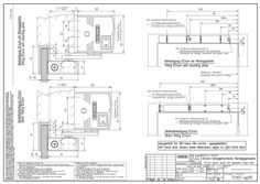
ECturn glass guide rail opposite hinge side
PDF | 150 KB
Key TSA 160 NT F pressing (link arm) right hand door
DWG | 248 KB